
CHANNELS

infoTECH Feature
Digital Ceiling PoE switch Increases Efficiency and Cost Savings for Connected Devices
 By Biju Oommen
.jpg)
In a smart building, smart city scenario and in the Internet of Things (IoT) realm, deploying digital ceiling Power over Ethernet (PoE) switches to deliver network connectivity and PoE to PDs (Powered devices) is beneficial. The deployment strategy of delivering power and data safely over the same Ethernet cable pairs equates to substantially increased efficiency, cost savings, and ease of installation. To achieve that, digital ceiling PoE switches support many features and technologies. Let’s briefly discuss some of them.
- PoE-BT (IEEE (News - Alert) 802.3-bt), the latest standard, supports delivery of up to 90W of power reliably and safely over four pairs of Cat-5e and above cabling systems. It is backward compatible with PoE-AT (IEE 802.3at, which supports up to 30W over two pairs) and PoE-AF (IEEE 802.3af, which supports up to 15W over two pairs). Normally, when the PD tries to consume power beyond the class maximum, the port would be shut down, but with the PoE extended-BT-power-mode feature turned on, the network switch will allow the PD to consume a little extra power beyond the maximum power for that class (e.g., 93W instead of 90W).
- PoE priority, can be set individually for each of the network switch PoE ports to low, high or critical. This helps prioritize which of the ports will be powered first or last while starting up and disconnected first or last when the power budget on the switch is exceeded.
- PoE-BT uninterruptible power feature enables the network switch to continue providing seamless uninterruptable power to the PDs, even when it is performing a software reset or device restart or when we are activating the alternate software image.
- STP, RSTP and MSTP come in handy, as you can prevent network loops that cause broadcast storms. Offering redundant backup paths between network switches, it will ensure that, at any given time, only one path is active among the many possible.
- Link aggregation using LACP allows us to use multiple ports in tandem to create a single logical link for increased redundancy, for higher availability, and to increase the throughput beyond the capability of what one switch port can offer.
- Private VLAN is a feature that permits filtering of outgoing destination port traffic. Packets received on a port can be sent only to destination ports that are part of a port group.
- When port isolation is turned on, those isolated ports are prevented from sending packets to each other. However, they can communicate normally with all the other switch ports. A loop protection feature can prevent network layer 2 loops by sending loop protect protocol packets and shutting down interfaces in case they receive loop protect packets from themselves.
- IGMP snooping is the activity of listening to IGMP network traffic to control delivery of IP multicast packets. The network switch listens to IGMP conversation between hosts and routers and maintains a map of the ports that the IP multicast traffic should go through, while filtering the IP multicast traffic from switch ports that do not need those IP Multicast packets. This conserves bandwidth on those links.
- Port Mirroring allows us to set up a dedicated port so that it can receive Tx and or Rx traffic from one or more ports.
- IEEE 802.3az Energy Efficient Ethernet aids in lower power consumption during periods of low data activity, thus reducing the total power consumed by the network switch PoE ports.
Microchip Technology (News - Alert) Inc., through its Microsemi subsidiary, offers the PDS-408G, a digital ceiling switch, which comes equipped with support for the above-mentioned standards and features. (Please refer to Fig. A. Microchip Technology’s Microsemi PDS-408G digital ceiling PoE switch).
A plenum-rated network switch such as the PDS-408G can be installed in the ceiling to provide automatic PoE power based on PoE PD device class and data connection concurrently for applications and systems such as:
- Facility access and management systems
- HD video door systems
- IP video encoder/decoders
- IP intercom speaker/microphone systems
- IP badge readers
- Building automation and control (BAC)
- HVAC controllers
- IP PTZ surveillance cameras
- DECT VoIP base stations
- IP network door controllers
- Smart PoE Lighting
- Public address systems
- Digital signage
- Wi-Fi access points
- Variable air volume (VAV) controllers
- Damper actuators
- Air flow sensors and IoT sensors
- PoE LTE (News - Alert) small cells
- IP clocks
- IP audio and video conferencing equipment and much more.
Thus, a multitude of devices can securely connect to IP-based smart building control systems, energy monitoring/management, and building security monitoring/management applications. This enables us to control, command and collect usage data, which is very beneficial.
PDS-408G as a power sourcing equipment (PSE) provides gigabit Ethernet to the connected devices and centralized power management for the connected PoE devices. PDS-408G’s 4-pair PoE technology permits you to deliver 90W PoE power over 4 pairs very efficiently, while offering savings in cable loss. When the PDS-408G is powered by an uninterruptible power supply (UPS), the PDs can continue to receive power even, during power interruptions.
Hence, the PDS-408G will be the focus of our discussion and the ensuing functional and interoperability testing. You can access the datasheet for the PDS-408G here: Microchip Technology’s Microsemi PDS-408G
The Microsemi PDS-408G supports features and functions such as:
- Total PoE power and full power: Maximum available PoE power 480W (8 ports x 60W = 480W. Any of the 8 ports can go up to a max 90W subject to the power budget of 480W
- Ports: 8x10/100/1000Mbps IEEE802.3bt compliant PoE ports with backward compatibility to IEEE80.3at/af. Legacy PoE detection mode for pre-standard PDs. Highly power efficient as standby power consumption less than 10W + uplinks ports-2x copper 10/100/1000 Mbps, + 1xSFP slot for 1Gbps SM/MM Fiber or 1Gbps copper transceiver, atotal of 8+3 ports
- Plenum rated and passive cooled (no fan) for improved reliability and silent operation
- Support: IEEE 802.3btPower over Ethernet (PoE) up to 90W; Ethernet 10/100/1000; IEEE 802.3, 802.3u, 802.3ab, 802.3z; IEEE 802.3x Flow control and back pressure; IEEE 802.3ad port trunk with LACP; Spanning Tree STP/RSTM/MSTP; IEEE 802.1D, 802.1w, 802.1s; IEEE 802.1ab LLDP; IEEE 802.1Q VLAN tagging; IEEE 802.3az energy efficient Ethernet; port isolation and private-VLAN; IGMP snooping (IPv4, IPv6, IGMP Snooping v1-v3 including IGMP Querier); port mirroring (Mirror Rx, Tx, and both); Link aggregation (IEEE 802.3ad LACP or static)
- Management: Web HTTP/ HTTPS (encrypted TLS v1.2), ACL access list for enhanced secure user access, Telnet, SSHv2, SNMPv1, v2cand v3, RADIUS/TACACS user authentication
- Software upgrade over HTTP, TFTP while software updates are being carried out, PoE delivery to connected PoE devices are maintained
Let us, now conduct the functional and interoperability testing of the PDS-408G. During the test, we will deliver PoE power to the PDs and field real-time streaming media, video traffic, place inbound and outbound voice and video calls.
FUNCTIONAL TESTING
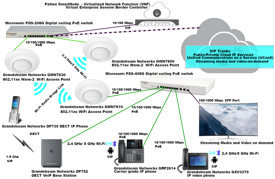
The test setup consisted of the MicrosemiPDS-408G (software release version 1.13), PoE firmware (24034356.1056.003) and the following systems (Please refer Fig. B. Functional and interoperability testing of Microsemi PDS-408G digital ceiling PoE ethernet switch):
- Grandstream Networks GXV3370 IP video phone main software release version 1.0.1.55
- Public SIP trunk services/UCaaS, streaming media and video-on-demand
- Grandstream Networks GWN7630 802.11ac Wave-2 Wi-Fi access point running software version 1.0.9.12
- Patton (News - Alert) Virtual SmartNode (vSN) running software version Trinity 3.16.0-19083 on Oracle VM VirtualBox hypervisor version 6.0.10. It provides SIP registrar services and SIP demarcation from the public SIP trunk/UCaaS provider in the cloud while maintaining interoperability and interconnectivity
- Grandstream Networks GWN7600 802.11ac Wave-2 Wi-Fi access point running software version 1.0.9.12
- Grandstream Networks DP752 DECT VoIP Base Station with the DECT wireless phones DP 730, DP 722 running software release version 1.0.11.2
- Microchip Technology’s Microsemi PDS-208G Digital Ceiling PoE switch with software release version 2.53 for network connectivity and PoE delivery
- Grandstream Networks GWN7610 802.11ac Wi-Fi access point running software version 1.0.9.12
- Grandstream Networks GRP2614 carrier-grade IP phone running software version 1.0.1.6
Powered the PDS-408G, logged into the PDS-408G using a browser. On the web-based GUI, the left panel provided all the switch configuration and view options, including: Overview, Network (IPs MAC), Access Control, VLAN, PoE-BT-Power, Spanning Tree, SNMP, RADIUS TACACS+, Aggregation/LCP, LLDP, Port Isolation, Loop Protection, IGMP Snooping, Port Mirroring, Maintenance, Diagnostics etc. It’s basically everything that relates to the management and provisioning of the PDS-408G. We clicked/navigated and selected appropriate values for:
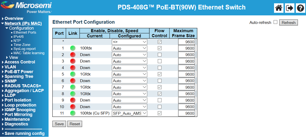
Network (IPs MAC) > configuration > ethernet ports for ethernet port configuration (Refer to Fig. C. PDS-408G Ethernet Port Configuration), >IP v4/6 for DNS servers, IPv4/IPv6 interfaces and IP routes (default-gateway), >NTP-enabled NTP configuration, >Time zone configuration.
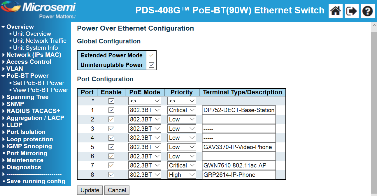
VLAN > configuration for global VLAN configuration and port VLAN configuration, PoE-BT Power > set PoE-BT power for PoE configuration (Global configuration, extended power mode and uninterruptible power), port configuration (enable PoE, PoE mode 802.3BT or legacy), priority (low, high, critical), Terminal type/description.
Spanning tree > configuration > STP configuration (STPbridge configuration and STP port configuration).
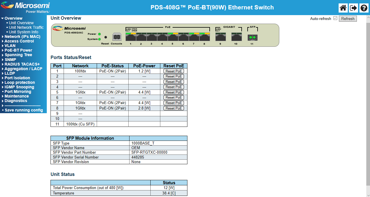
LEDs on the PDS-408G convey the operational status of the ports. When, PoE LED (right) is green, power is delivered over 4 wire pairs; when it is orange, power is delivered over 2 wire pairs; when blinking green, there is a PoE error such as a short or overload. When the link LED (left) is green, the port link is up; when it is blinking, it is transmitting data and the link is up. As a network switch administrator, you can remotely power down the connected devices during periods of low use or power-cycle the devices. If we clicked on overview > unit overview, the unit overview page provided us the status of the port (network connectivity, PoE-status, PoE power usage, reset PoE, SFP module information, total PoE power consumption, switch temperature, etc.) It provided all essential information in real time.
Here, we could also reset any of the connected PoE PDs. We clicked on reset PoE and PoE power was shut down (PoE disabled) temporarily for that port for a few seconds, and then PoE power was restored (PoE Enabled). (Refer Fig. D. PDS-408G Unit Overview)
If we hovered the mouse on a port, it displayed the port network status, and when you click on the port, it opens a page with the port statistics details for that port. We configured the requisite parameters and connected our test PDs. Thus, the PoE and network connectivity for the GXV3370 IP video phone, DP752 DECT VoIP Base Station, GRP2614 carrier grade IP phone GWN7600 and GWN7610 Wi-Fi APs were provided by the Microsemi PDS-408G Digital Ceiling PoE switch.
We then clicked on PoE-BT, set PoE-BT power and put a check mark against uninterruptible power, updated and then saved running configuration. We restarted the PDS-408G (maintenance > Reset & restore unit > restart device) from the web GUI interface and observed that all the connected PDs continued to receive PoE power as the switch was restarting. (Refer to Fig. E. PDS-408G Power Over Ethernet Configuration). Next, we clicked on, maintenance > software update > select active image and activated the alternate image. Yet again, during the re-activation of the alternate image, all the connected PDs stayed up. This indeed is a very valuable feature, as we may need to restart the PDS-408G and or activate a software image after an upgrade to a new version, without powering down the connected PDs. This is especially vital for LED-light fixture PDs, as we will want the lights to stay on, even when the PSE is being restarted.
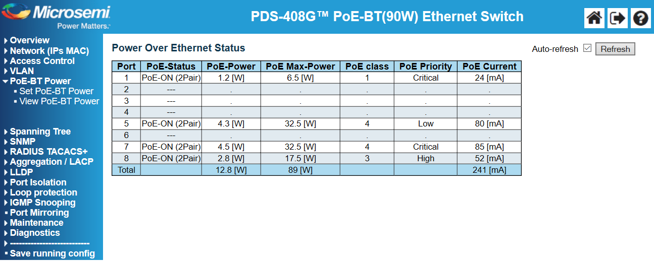
Under view PoE-BT power, for each port, it showed us important and relevant information in real time, such as the PoE status, Poe power (actual PoE power consumption by PD), PoE max-power (maximum power that PD can consume based on its class 0-8), PoE class (detected PoE PD class), PoE priority (user configured PoE priority) and PoE current (PoE current consumed by the PoE PD). (Refer to Fig. F. PDS-408G Power Over Ethernet Status)
The test devices powered up and successfully registered with the ITSP’s external SIP trunk/UCaaS call control platform in the cloud. We were able to run applications that required high bandwidth and low latency, such as real-time voice, video calls, streaming media and video-on-demand. The Patton Virtual SmartNode (vSN) as a Virtual Network Function (VNF) Session Border Controller (SBC) provided SIP registrar services and SIP demarcation from the public SIP trunk/UCaaS provider in the cloud, while maintaining interoperability and interconnectivity. Its provisioning and management were accomplished using the Patton Cloud, a single portal network orchestration tool.
PDS-408G’s configuration was easy and straightforward. From an administrator’s perspective, we were impressed by the simplicity of installation and versatility of the PDS-408G. We changed the PDS-408G settings using the web GUI. Settings also can be changed using CLI and/or telnet.
PDS-408G’s functions and features were easily accessible, thanks to its web-based management interface and we found that a simple deployment is just a few clicks away. The well laid out screens meant we just needed to follow the intuitive onscreen menu layout. Modification and configuration of PDS-408G’s features using the web-based Microsemi management interface gave us complete control of the unit’s administration, monitoring, reporting and alerting functions.
Conclusion
During our testing, Microchip Technology’s MicrosemiPDS-408G Digital Ceiling switch delivered both PoE and reliable connectivity and it was easy to deploy and manage. It is indeed a plug and play Digital Ceiling PoE switch.
Edited by Erik Linask
|
|
FOLLOW US | |
|
|
infoTECH Headlines
Exchange Server Recovery: Best Practices for Production Environment
Beyond the headlines: translating the Mythos risk for business leaders
cdmon Supports Online Businesses with Hosting, Domains and Digital Infrastructure Services
Why Hiring a Commercial Electrician in Keller Matters for Business Safety, Efficiency, and Growth
Are You Giving Your Agentic AI Too Much Access? Is it Impacting Compliance?
The Future of AI: Autonomous Training Models That Learn Continuously
How to Migrate from One Microsoft 365 Account to Another?
Simulating Your Worst-Case Scenario and Keeping Tabs on New Threats Using AI Systems
From Reactive to Proactive: Using AI to Hunt BEC in Real Time
Strengthening Tampa Businesses with Expert Cybersecurity Solutions
Rich Tehrani
infoTECH Whitepapers